Simon Frankau's blog
Electronics for Newbies: The LCM555
Having not played with any electronics for something over a decade, I thought it'd be time to whip out the breadboard again. So, I thought I'd start with the bog-standard newbie construction, a 555-based blinking LED. This time round, for fun, I thought I'd use an LCM555 CMOS-based 555, since it apparently wouldn't do bad things to the power rail, which is nice, as my eventual goal was to use the 555 as a clock for some sequential circuitry while testing. I looked at the reference circuit design, plugged it into a surplus Nokia phone charger (the LCM555's got a nice, wide supply range, so I didn't think too hard here), plugged it all together, and... nothing.
So, yay, electronics debugging time! For the first time in my life, I actually bothered to learn how the 555 works, rather than treat it as a magic incantation for making something blink. It's actually rather straightforward and neat, but I'd never bothered getting the datasheet before. Once I understood how it worked, I realised I'd been choosing resistor values that were basically shorting it. You'd have hoped something might mention not to do this, but noone seems to bother. D'oh.
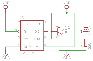
I fix that up and... nothing. Even a fresh chip doesn't work. I'm now a little frustrated, but at least I understand how it's supposed to work. I now set up a simple test circuit which removes all that faff with capacitors, so that it should basically run in a steady state and show its hysteresis:

I plug this in, and it behaves weirdly. The the lower level switches on, but then it immediately switches off above this level - there's no hysteresis up to the higher level. Why this asymmetry between the levels? Could it be something to do with the adjustment pin ('CV')? Nope. The circuit should be quite static, without a capacitor, so I shouldn't be seeing any glitchy behaviour. However, when I put more bypass caps in, it goes from on/off to on/slight glow. Hmmm.
Argh. Sticking a multimeter in min/max mode voltage on the power supply reveals a rather high max, and a min of zero. Frequency? 100Hz. Yay, we have a fully-rectified but unsmoothed, yet alone regulated power supply. I'd really assumed that thing would be regulated. Apparently not!
The attachment of a 9V battery (they're convenient in that you can attach them using crocodile clips, if you don't have a proper snap), and everything works fine!
So, now I've been learning up on power supply theory. Horowitz and Hill has been sitting on my shelf for years - I tried reading it front-to-back before, and wedged somewhere near the start of Chapter 3, but I've now zipped through the whole of the power supplies chapter. I only needed about 3 pages, but it's fascinating, and each chapter seems to be about as self-contained as it can be, so it's been surprisingly engrossing.
I could just power my future projects off batteries. Not a 9V, since many of the digital chips I'm looking at max out not far over 5V, but maybe a set of rechargeable AAs. However, I now want to play with all the options, so I've ordered a few battery holders, plus the chips, caps etc. for both linear and switching regulators. I think the switching regulators should be overkill, but at least fun to play with.
We'll see how it goes.
Posted 2010-03-03.