Simon Frankau's blog
Electronics for Newbies: Oscillator practice
Some people might suggest that the theory of crystal oscillator design should perhaps precede constructing such an oscillator. I thought a) I'd have a go by doing, and b) It's easy, anyway, right?
Consulting Horowitz and Hill plus a minimal bit of research on the internet indicated that I wanted a Pierce oscillator, that you need to get capacitors which match the crystal, and that otherwise the series and feedback resistor hardly matter.
So, I got myself a 4MHz crystal and 32kHz crystal, both with their appropriate capacitors. I used a 10k series resistor, and a 10M feedback resistor. I breadboarded up the circuits, attached my 'scope and... nothing. Hurrah. The 4MHz generated nothing, and the 32kHz generated noise.
So, I lightly investigated the theory, to see which tweaks might make the things work. The 4MHz crystal wasn't too difficult to twist into working. Replacing the 10k series resistor with 220 Ohms (!) made it work, at least some of the time. 220 Ohms is about all I have, otherwise, as most of my resistors are either pull-ups, or current limiters for LEDs - That's all I needed for simple logic circuits, I thought. Either way, it worked, as can be seen in my little picture.
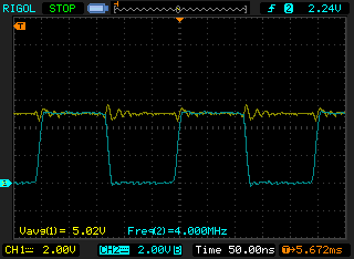
The yellow trace is the power supply. Perhaps I should have put more decoupling in? I'll experiment later. My skimming of the internet, trying to find clues as to the problem lead me to a couple of useful application notes - Microchip's AN849 and ST Microelectronics's AN2867. The former seems to concentrate on debugging broken oscillators, while the latter on using maths to design them right! In my current situation, the former was what I approached first. With the small resistor, I was worried about overdriving, so I moved the resistor to the other side of the capacitor and measured either side of it to get the potential across it (using the exciting 'maths' mode of my 'scope).
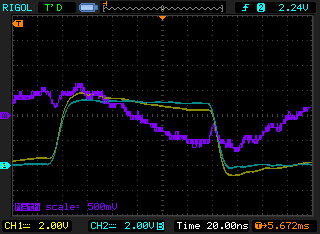
It looks like it could be just a little overdriven, or it could just be the way I'm measuring. Of course, measuring all this stuff with an oscilloscope probe is rather fun, since the probes have similar capacitance to the caps actually designed into the circuit! The other fun point is that as it's really just a little feedback circuit, with different gains at different frequencies, the oscillation in a badly designed circuit (e.g. mine) can vary on a per-startup basis. Sometimes there might be no oscillation, and at other times a different mode may appear. I have much to learn!
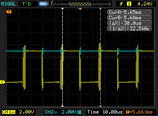
Finally, I tried my hand at getting the 32kHz crystal working, which had been much more uncooperative. With much faffing, I got it to work (unreliably) with 18pF capacitors, 30M of feedback resistance, and 115k of series resistance. As you can see from the screenshot, it's incredibly noisy. Next stop, I'll look up the theory and do some maths to see if I can make it work better!
Posted 2010-06-27.