Simon Frankau's blog
Dumb generation of VGA video
Before I start, I should emphasise that I'm generating VGA voltage levels, to a VGA signal pattern, over a VGA connector, but not using a standard VGA resolution or pixel clock. Fortunately, I've had a monitor capable of multisync since 1995, so I don't see this as being much of a problem.
Following up from my post on VGA signals, I decided to try to make the very dumbest "VGA" generator possible. The idea is to hook up a counter to an EEPROM/Flash memory, and then hook the data pins up to the VGA connector. The sync and video signals would all just be directly recorded in the data.
The basic circuit was straightforward, and whipped up on a breadboard. I used a 2MHz oscillator, as that's what I had around, and it was a nice, low frequency to send signals around a breadboard with. The downside is that each on-screen "pixel" would be rather wide, but I'd live with it. This fed into 3 daisy-chained 74HC590s. I discovered that while chaining the RCO (ripple carry out) into CE (count enable) worked for connecting the first and second stage, it didn't work between the second and third stage (go work out why :). Instead I reconfigured it, as suggested in the data sheet, to feed the RCO of the second stage into the CPC (counter clock input) of the next stage. I now had a 24-bit counter to address whatever memory I put in. It appears ripple delay wasn't a problem.
For memory, I selected a 29040 512KB Flash memory. I'm sure there's a tiny processor in there, so my VGA display is not technically CPU-free, but, well, we could pretend it's just a ROM. I'd been using EEPROMs in the past, but I'd noticed that Flash memories are bigger and cheaper, so, well, that's what I used.
I cobbled up a video mode whose total pixels-per-frame neatly fits into the memory (actually, fitting neatly into 32KB, but I repeated it throughout the memory's address space - I guess I could have created an animation), and wrote a little Lua script to generate a memory image to generate the signal.
The 8 data bits of the memory then drive the lines of the VGA connector. H- and V-sync are driven directly by the TTL-compatible output of the memory. The remaining 6 pins give us 2 bits of red, green and blue. 64 colours is way more than I ever had on my ZX Spectrum. To get these colours I put in a resistor in series with each of the pins producing colour, so that when both pins are on, with a voltage divider with the 75 Ohms at the monitor end of the cable, the TTL signals become a 0.7V VGA-like signal.
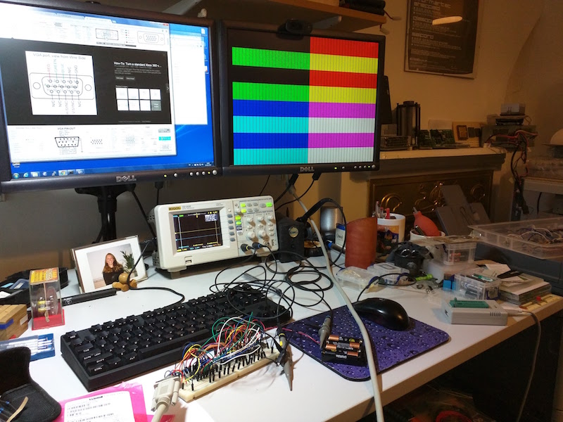
And... the end result works! Here it is, with just 3 bits of colour (I was a little impatient!):
I wired up the other 3 bits, and, well, got the colours:
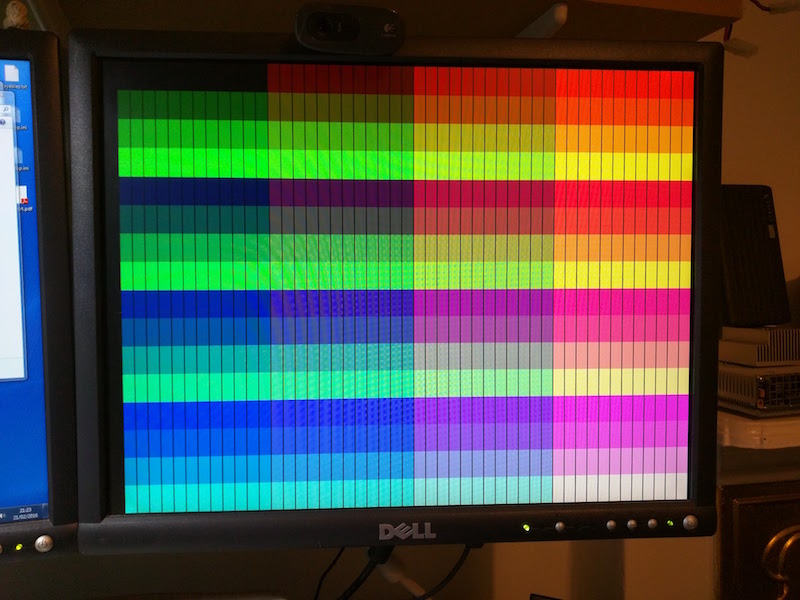
You can see the invidual horizontal pixels which, as predicted were rather wide (16 times as wide as if we'd run off a VGA-like pixel clock). However - there's a big vertical stripe down at the end of each pixel. What's that about? When I dig the oscilloscope out, I see big piles of transients between the pixels where the memory output is changing. If I put an octal latch on the output of the memory, clocked on the oscillator to make the signal cleaner, the stripe goes away:

I'm a Bad Person as the latch I have triggers on the same edge as the address changes on, so I'm probably breaking set-up and hold times, but the chip doesn't mind - if I pop an inverter on the clock signal, it makes no difference to the video image.
I have quite a few plans from here. I'd like to try to up the frequency of the oscillator, to get higher resolution, and I'd like to use the high bits of the oscillator to trigger the high bits of the memory, to generate animation. Oh, and I plan to get the code and schematic documented, and get the thing up on github. Fun, fun, fun!
Posted 2016-02-28.