Simon Frankau's blog
Electronics for Newbies: The simplest possible microcomputer
So, the last time I did any electronics, according to my blogging, was 2010. I got stuck with some crystal oscillators which behaved in an annoyingly analogue fashion, and my plan was to go model them in SPICE to understand them better. Somewhat later, after having children eat up a few years of time, I realised that I don't actually have any interest in becoming an analogue electronics expert, and I might as well stick to the digital electronics (which is noisy and messy enough as it is!
So, getting back to the main plot, I'd rather like to build a simple 8-bit microcomputer. Z80-based, for preference. This is getting more and more difficult to justify, given that single chip microcontrollers are getting ludicrously powerful, let alone what you can get for hobbyist embedded stuff - Arduino and Raspberry Pi (hi Eben!) to name just a couple. It's almost a bit difficult to avoid cheating, since you'll probably want to use some modern interface bits and pieces, but it's far too easy to, well, make it too easy for yourself.
As it is, I'll be using nice modern software tools - cross-assemblers and schematic editors, modern docs off the internet, etc., but I hope to at least partly keep to the spirit. When it comes to I/O, I'll probably just tack on a modern intelligent LCD and PS/2 keyboard, despite both of them effectively cheating, once basic RS232 serial is working. I see little point in trying to give myself too much pain in a basic project!
First step, though, I wanted to create the simplest possible Z80-based system. To do this, I created a single-byte hard-wired ROM out of, well, 8 resistors. This is what I mean:
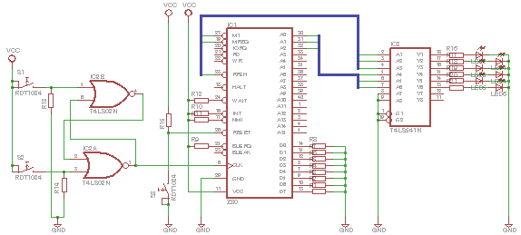
Specifically, I wired up the data bus to produce NOPs. The CPU should just step through memory, doing a combination of opcode reads for the NOPs and refresh cycles for the Z80's DRAM support thing. The plan was that I could then watch the pins of the CPU as it does its stepping, with my manual clock cycling. I put in the flip-flop to make sure things were nicely debounced. Pretty much everything had a 10k resistor between it and a power rail, having had previous experience of unnecessary accidental shorting breaking stuff. I've also missed out decoupling caps and the rather useful power LED to remind me not to faff with stuff while it's on.
So, I powered up the circuit and was mildly surprised to see it running through the following cycle of states (sampled consistently in clock high or low state - I forget which, and don't care much :)...
| Address | /M1 | /RFSH | /MREQ | Description |
|---|---|---|---|---|
| 0 | 111 | 111 | 111 | Init |
| 0 | 00 | 11 | 10 | Opcode |
| 0 | 111 | 001 | 101 | Refresh |
| 1 | 11111111 | 11111111 | 10011111 | ? |
| 2 | 00 | 11 | 10 | Opcode |
| 1 | 111 | 001 | 101 | Refresh |
| 3 | 11111111 | 11111111 | 10011111 | ? |
| 4 | 00 | 11 | 10 | Opcode |
| 2 | 111 | 001 | 101 | Refresh |
| 5 | 11111111 | 11111111 | 10011111 | ? |
| 6 | 00 | 11 | 10 | Opcode |
| 3 | 111 | 001 | 101 | Refresh |
| 7 | 11111111 | 11111111 | 10011111 | ? |
Each row represents several cycles where the address bus remains the same. The 0s and 1s are the values of that line for each of the cycles at that address. The very first line is post-reset initialisation. After that, there appear to be cycles of three different patterns...
Specifically, it shows is the odd and even addresses behaving differently. According to the M1 line, opcodes are read at addresses 0, 2, 4 and 6. After reading the opcode, there are refreshes, running at once per instruction, at addresses 0, 1, 2 and 3, and then some non-opcode read at addresses 1, 3, 5 and 7, taking 8 cycles.
So, what's that about? Odd and even instructions apparently behave differently. Perhaps it's not actually a pair of instructions, but treated as a single instruction. The total instruction time is 13 cycles. An online search reveals that one of the few instructions taking 13 T-states is DJNZ, in the 'not jumping' case. It is an instruction with a single byte operand. It's opcode is... 0x10. Perhaps my D4 pull-down line wasn't working properly?
Sticking a 'scope on the pins showed nothing surprising. However, if I applied 0V directly to the pin, rather than through a breadboard connectiong, it started working properly. I expect a nice floaty CMOS input would be fine for showing one thing on the scope, and something else to the CPU. Fun, fun, fun.
So, my hardwired program was apparently 'DJNZ 0x10'. I now have a better understanding of the Z80's instruction cycle (including a realisation of quite how slow old CISC processors are - how many cycles to complete a simple operation?!). I also have a bit of a worry about how painful debugging a non-trivial microcomputer may be. If a circuit as simple as this needs debugging and investigation, how much fun will a real computer be?!
Posted 2013-07-28.