Simon Frankau's blog
Reading from a floppy drive with an oscilloscope
I feel I've more-or-less conquered VGA, so perhaps it was time to conquer another mysterious technology of my youth: floppy disks. At the time, low-level details always seemed rather rare, and even now useful details are thin on the ground - while the Internet gives us a tonne more information on most stuff, floppy disk drives are sufficiently irrelevant that it's a bit thin on the ground for FDDs.
Step #0: Power. How do I power the drive before I start playing with it? The standard FDD connector takes in 5V and 12V, but fortunately my 3.5" drive (yes, I have a 5.25" drive, but I thought I'd play with 3.5" first) has N/C on the PCB for the 12V line, so I only provided 5V, and it worked!
Next step - control lines. The obvious starting point is the pin-out. It's pleasantly straightforward. I assumed the levels were TTL. Reading the level on the inputs suggests passive pull-up with active pull-down required to trigger functions. Pulling down the drive B motor line (which becomes drive A after passing through the twist in the floppy cable) makes the motor run (but only if there's a disk in the drive). Pulling the drive B select line low makes the light on the front light up (ditto only if there's a disk in the drive).
The lines from the drive are only driven if the select line is low. This too is actively pulled low, expecting passive pull-up, which makes sense for a kind of wired-or active-low bus. At this point, I can use the step and direction line to manually step to track zero - it appears that if you don't pull the direction line low it steps to lower track numbers, so stepping to track zero is pretty straightforward.
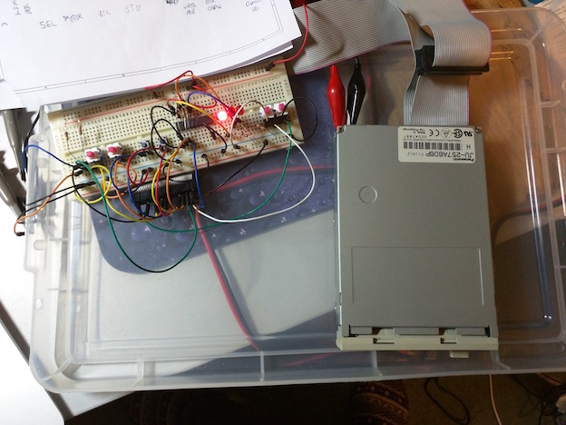
At this point, my set-up looks something like this:
And now, reading the disk. When the motor's running (and drive select line low), the the index line pulses at 5Hz, so the drive's running at 300 RPM. If I attach an oscilloscope to the data line, triggering on the index line, you can see the data pulses:
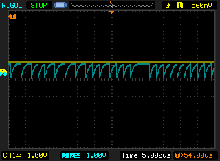
You can see the ticks down when the pulses happen, and I assume the curve up is some kind of RC curve from the pull-up resistor I added. Next stop: saving the signal and extracting the data.
Posted 2016-04-19.