Simon Frankau's blog
VGA(ish) signal timing
In 1995, I had a relatively brutal introduction to VGA signal timings. I wanted to set up XFree86, for which you had to specify the exact signal timings, and the documents were impressively confusing to a teenager, yet also full of dire warnings that GETTING THIS WRONG COULD DESTROY YOUR MONITOR. Somehow I got through it all and managed to get a working X11 set-up, largely by cargo-culting the examples. Kids these days (and myself) have it easy, etc.
Fast forward a decade, and I saw Eben Upton bit-banging a VGA signal using an AVR. This was his idea of Raspberry Pi at the time - a small, simple and understandable computer to teach kids to program. Like an early micro, the AVR could bit bang the screen as it was being rasterised, and do its computation in the vertical fly-back, and you could run an interpreted language on top of that. Of course, the final RPi was something incredibly different, and stunningly more powerful, but it was awesome to see it evolve from that.
Roll forward another decade (argh!). I've been interested in generating my own VGA signal for years - not in software, but as another hardware project, building my own graphics card. It's way down my projects list, but this evening I thought I'd make a little step on the road there - I wanted to both refresh my memory and make sure I fully understood how a VGA signal works. For the moment, I'm ignoring the analogue details - I want to get a handle on the timings.
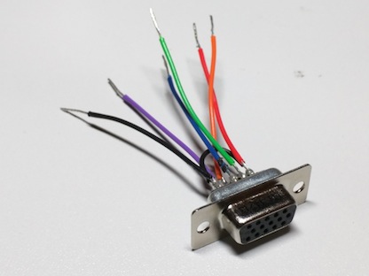
There are a number of websites describing VGA signals, but I never really trust those timing diagrams, especially with all the elided data. So, I whipped out my oscilloscope, wired up a VGA connector, plugged it into my monitor cable, and got the actual waveform.
My plan is to describe the waveform algebraically. There are three sets of lines of interest - the RGB colour lines, horizontal sync and vertical sync. I'll create a few states based on what's being placed on those lines at a particular point in time:
- DATA RGB lines contain data, H and V sync low
- BLANK RGB lines low, H and V sync low
- HSYNC RGB lines low, H sync high and V sync low
- VSYNC RGB lines low, H sync low and V sync high
- HVSYNC RGB lines low, H sync high and V sync high
All of the above represent the lines being held for one pixel clock time unit. From this, we can construct some signals. I'll use '* n' to represent a signal pattern being repeated n times, and '+' to mean signal concatenation.
- DATA_LINE ::= HSYNC * hs + BLANK * hbp + DATA * hres + BLANK * hfp
- BLANK_LINE ::= HSYNC * hs + BLANK * (hbp + data + hfp)
- VSYNC_LINE ::= HVSYNC * hs + VSYNC * (hbp + data + hfp)
- FRAME ::= VSYNC_LINE * vs + BLANK_LINE * vbp + DATA_LINE * vres + BLANK_LINE * vfp
One thing to note, which seems to get left out of some timing diagrams, is that the H syncs keep going through the vertical blanking period - it's just that there's no image data during that period. The vertical sync signal edges are sync'd to the rising edge of the horizontal sync signal.
The variables are as follows, including example values for 800*600 at 75Hz:
- hs Length of horizontal sync. 80 pixels.
- hbp Horizontal 'back porch'. 160 pixels.
- hfp Horizontal 'front porch'. 16 pixels.
- hres Visible horizontal resolution. 800 pixels.
- vs Length of vertical sync. 3 lines.
- vbp Vertical 'back porch'. 20 lines.
- vfp Vertical 'front porch'. 1 line.
- vres Visible vertical resolution. 600 line.
From this we can see there are 1056 pixel clocks per line, and 624 lines per frame, and at around 75 frames per second, this is 1056 * 624 * 75 = 49420800 pixels per second. I believe at 49.5 MHz clock is used.
Posted 2016-01-26.